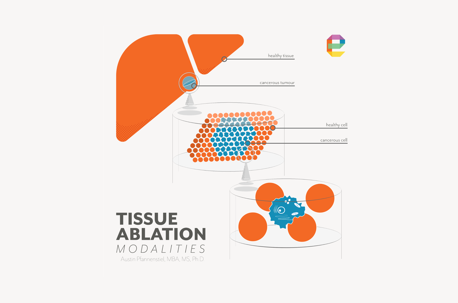
In pulsed field ablation (PFA), also called irreversible electroporation (IRE), or pulsed electric field (PEF), the treatment zone is defined by the electric field distribution between electrodes. Importantly, PFA does not rely on heat to destroy tissue, avoiding many of the difficult-to-predict thermal diffusion effects that complicate thermal ablation modeling.
The field either exceeds the threshold for irreversible cell membrane disruption at a given location, or it does not. That binary, field-governed mechanism makes PFA uniquely amenable to computational prediction. And it makes computation uniquely important.
Get the model right, and you can predict the treatment zone's shape, size, and margin with engineering precision before a single animal study begins. Get it wrong, and the errors show in explanted tissue or, later, in clinical outcomes.
This article describes how computational modeling works for PFA/IRE/PEF systems, what the critical inputs and limitations are, and how our team at Engenious Design uses simulation as a primary design tool across the PFA programs we support.
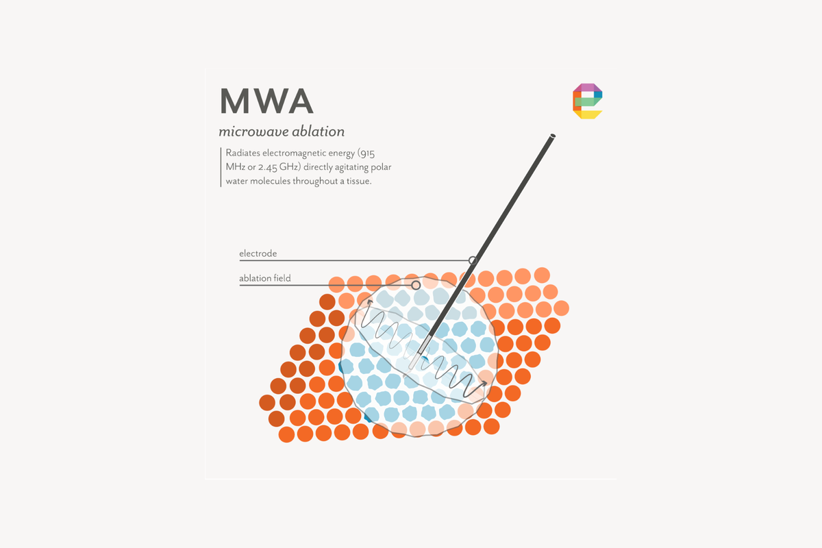
Our deepest computational modeling experience is in microwave ablation (MWA), where coupled electromagnetic and heat transfer simulation has been central to directional applicator development work. The principles of field-based simulation carry directly to PFA, and the field-threshold approach PFA uses is in some respects more tractable than the coupled thermal problem in MWA.
The electric field distribution inside tissue during PFA is governed by a partial differential equation that describes how electrical current flows through a medium with a given conductivity distribution and voltage gradient across it. Solving this equation across the three-dimensional geometry of the electrodes, the target tissue, and surrounding structures gives the electric field magnitude at every point in the model.[1,2]
The critical output is not voltage or current — it is the electric field magnitude at every location in the tissue. Points where the field exceeds the irreversible electroporation threshold will be destroyed. Points where it falls below the threshold survive.
The treatment zone boundary is the surface in three-dimensional space where the field equals the threshold. This threshold-based framework is the foundation of all IRE treatment planning and applicator design simulation.[3,4]
The electroporation threshold is not a fixed number. It depends on the tissue type, the pulse duration, the number of pulses, and the repetition frequency. Experimental characterization of the threshold for a given tissue type and pulse protocol is therefore a prerequisite to building a predictive model, not a validation step that comes after.
Fortunately, there is existing literature that can give us a starting point. Published threshold values for liver tissue range from approximately 500 to 1,000 V/cm depending on the pulse protocol, with lower thresholds reported for longer pulse durations and higher pulse counts.[5,6]
Cardiac myocytes, due to their elongated geometry and tight electrical coupling, reach the irreversible threshold at lower field strengths than most soft tissue parenchymal cells — a physiological difference that is central to PFA's selective tissue effects in cardiac applications.[7]
The standard approach to threshold determination for a new application is to run ablation experiments in in vivo tissue at known voltage and electrode spacing settings, measure the resulting ablation zone boundary from post-procedure imaging or histological examination of resected tissue, and then back-calculate the electric field value at that boundary from the model.
The field value that best predicts the observed boundary across a range of conditions becomes the working threshold for subsequent design calculations.[5,8]
Tissue electrical conductivity is the single most important material property input to a PFA model. It determines how the electric field distributes across the tissue volume, how much current flows for a given applied voltage, and how the field is perturbed by tissue heterogeneity.
A model built with the wrong conductivity value will predict the wrong treatment zone, regardless of how carefully the electrode geometry and threshold are characterized.[5,9]
Conductivity values for different tissue types are available in the published literature, but the range reported across studies is wide — often a factor of two or more for the same tissue type — reflecting genuine biological variability, differences in measurement methods, and differences between tissue types and their perfusion state.
For liver tissue, published conductivity values used in IRE models range from approximately 0.1 to 0.4 S/m.[5,9] Matching the conductivity value in the model to the specific tissue type and the conditions under which the experimental validation data were collected is essential to achieving accurate predictions.
Experience in conducting tissue experiments and a deep fundamental understanding of the biophysical factors, including underlying disease states, that affect tissue conductivity are critical in the development of refined computational models.
A complication that distinguishes PFA modeling from simpler static field problems is that tissue conductivity changes during the delivery of pulses. As cell membranes are permeabilized, the intracellular material becomes electrically accessible, and the overall conductivity of the tissue increases.
Published data show conductivity increases of two to seven times baseline in the regions exceeding the irreversible electroporation threshold.[9,10] This is not a small correction — a conductivity that doubles in the treatment zone will substantially redistribute the electric field, expanding the treated volume and altering the shape of the treatment boundary.
The standard approach to modeling this dynamic behavior is to represent the conductivity as a function of the local electric field magnitude using a smooth step function (typically a sigmoid or Heaviside function), where conductivity transitions from its baseline value to an elevated value as the field crosses the electroporation threshold.
This nonlinear conductivity model is implemented within standard finite element solvers (COMSOL Multiphysics is the most widely used platform in the IRE literature) and converges iteratively until the field distribution and conductivity are mutually consistent.[3,10]
A simpler static model — one that ignores conductivity changes — will systematically underpredict the treatment zone, particularly at higher pulse counts.
The geometric model of the tissue and electrode configuration is the scaffold on which the field solution is computed. For applicators, this geometry is imported from design drawings. For patient-specific treatment planning, it is reconstructed from medical imaging. The level of geometric complexity required depends on the question being asked.[4,11]
For applicator design, electrode geometry is the primary variable being optimized. Inter-electrode spacing is the strongest determinant of the field distribution: moving electrodes closer together increases the field intensity between them but reduces the volume of tissue that exceeds threshold. Increasing spacing spreads the field over a larger volume but reduces peak intensity.
The number of electrodes, their arrangement in space, and which pairs are energized simultaneously all shape the three-dimensional field distribution in ways that can be predicted by simulation before any prototype is built.[4,12]
Active tip length — the length of exposed, electrically conductive electrode within tissue — is an additional geometry variable with a direct and predictable effect on the treatment zone.
Longer exposed tips extend the field distribution along the electrode axis, elongating the treatment zone in the direction parallel to the electrodes, while shorter tips concentrate the field between the electrodes and produce a more compact, spherical zone at equivalent voltage and pulse settings.
Computational models and experimental studies confirm that active needle length is a significant determinant of ablation zone geometry alongside inter-electrode distance and applied voltage, with longer exposures producing larger, more elongated ablation volumes.[18,19]
For device design, active tip length is a tunable parameter that should be optimized in simulation before hardware is finalized, because it directly determines whether the treatment zone matches the intended clinical target shape.
One of the most useful outputs of a systematic simulation campaign is not a single predicted treatment zone, but an envelope of predicted zones.
For a given electrode configuration and number of electrodes, simulation can define the minimum treatment zone (at the lowest intended voltage, lowest pulse count, and closest electrode spacing) and the maximum treatment zone (at the highest voltage, highest pulse count, and widest spacing), with the nominal zone at the specified operating conditions falling between them.
This envelope defines the device's claimed performance range, directly supports the voltage and pulse parameter specification, and provides the empirical regulatory basis for the claimed indication.
The simulation can also quantify how the zone degrades with realistic electrode placement error — for example, a one-millimeter deviation from parallel — establishing the margin budget available for positional uncertainty before any animal study begins.[4,12,19]
This makes computational modeling the primary tool for applicator geometry optimization in PFA — not a validation step performed after the fact.
The simulation narrows the experimental parameter space from dozens of conditions to the few that are predicted to perform within specification, and it is the primary basis for electrode geometry selection before any animal study begins. In vivo validation then confirms the prediction against imaging and histological data rather than exploring parameter space from scratch.[4,12]
Most published IRE models begin with a homogeneous tissue domain — a single-conductivity block with electrode geometry embedded in it. This is the appropriate starting point for initial design work. It is fast, predictable, and sufficient to answer the primary geometric design questions about electrode spacing and array configuration.[3,4]
When the application involves tissue heterogeneity — different organ compartments with different conductivities, or critical structures like blood vessels, bile ducts, or nerves running through the treatment field — the homogeneous model breaks down.
Blood, for example, has a higher conductivity than soft tissue parenchyma. A large blood vessel running through the treatment field concentrates current into the vessel, creating a high-conductivity path that draws field away from surrounding tissue and can produce zones with more than 60 percent reduction in electric field strength immediately adjacent to the vessel.[13]
A homogeneous model in this geometry will overpredict field coverage in the shadow of the vessel, systematically misidentifying regions of potential incomplete treatment.
Incorporating tissue heterogeneity requires building a multi-domain geometric model in which each tissue type (tumor, organ parenchyma, vessel, duct) is assigned its own conductivity value.
For device development, this means building representative models that include the critical structures present in the intended clinical anatomy. For patient-specific planning, it means segmenting those structures from the patient's pre-procedure imaging.[13,14]
At the clinical end of the spectrum, PFA treatment planning follows a workflow similar to radiation therapy: import the patient's CT or MRI images, segment the tumor and surrounding critical structures, build a three-dimensional model of the anatomy, place electrode representations in the model at the planned positions, run the field simulation, and verify that the target volume is covered by the lethal field while adjacent critical structures are not.
This workflow was established for IRE of hepatic tumors adjacent to major blood vessels, where the redistribution of field by high-conductivity blood requires patient-specific modeling to ensure complete tumor coverage at a safe applied voltage.[14]
Patient-specific IRE treatment planning has been demonstrated in liver, prostate, and pancreatic tumor applications, with model-predicted treatment zones compared against contrast-enhanced CT and MRI imaging taken after the procedure and against histological examination of resected tissue.
Agreement between predicted and observed treatment zone boundaries in these studies is typically within one to two centimeters, with the largest discrepancies attributed to variability in tissue electrical conductivity and uncertainty in electrode placement.[8,14]
The field continues to mature rapidly, driven by the growth of cardiac PFA and the increasing commercial interest in IRE for solid organ oncology.
The largest remaining source of discrepancy between model-predicted and observed treatment zones is electrode placement error.
PFA requires multiple electrodes placed in precise parallel geometry — typically four to six needles within a few millimeters of their planned positions — and deviation from the planned configuration redistributes the field in ways that are difficult to compensate for intraoperatively.
Advances in robotic and navigation-assisted needle placement are directly addressing this gap. CT-navigated stereotactic IRE electrode placement has been shown to reduce mean needle placement error from 3.3 mm to 2.2 mm compared to conventional CT-fluoroscopy guidance, while also cutting procedure time from 87 to 27 minutes and significantly lowering radiation dose to both patient and operator.[20]
Dedicated robotic systems for multi-needle IRE insertion are also under active development, with robotic grid platforms achieving needle orientation deviations below one degree and placement accuracy within approximately 2.7 mm across a range of target depths and configurations.[21,22]
As these systems mature, the combination of patient-specific computational treatment planning and robotic electrode delivery creates a closed-loop workflow where the model defines the target configuration and the robot executes it with the precision the model requires to be predictive.
PFA is a non-thermal ablation mechanism at the cell level, but every electrical pulse delivered between electrodes deposits some energy as heat in the tissue.
For most PFA protocols, this thermal contribution is secondary — the electroporation threshold is reached well before temperatures rise to levels that cause protein denaturation. For protocols at the high end of the pulse count and voltage range, or for multi-electrode configurations that concentrate current density in a small tissue volume, the thermal contribution can become significant.[5,15]
In the thermal model for PFA, the rate of heat generated by the electrical pulses (which the electric field model computes) becomes the heat source term in a separate thermal equation that describes how that heat diffuses through the tissue and is removed by blood perfusion.
Solving both problems together — the electric field problem and the thermal problem — gives a complete picture of both the electroporated zone and any thermally damaged zone that coexists with it.[5,15]
The practical design implication is that pulse protocols should be characterized and modeled across their full operating range, not just at nominal settings.
The boundary of the thermal contribution zone moves with pulse count and power level in ways that are not always intuitive, and the regulatory question of whether any observed tissue effects are thermal or non-thermal requires the model to resolve the distinction.
Our team has built this type of coupled model for MWA — where the electromagnetic and thermal problems are similarly coupled — and the computational infrastructure and workflow carry directly to PFA thermal characterization.[15,16]
The computational model is not a background activity that produces charts for a report. It is an active design tool that drives specific hardware decisions.
In our experience developing field-based models for MWA and applying those methods to PFA programs, the following decisions should be directly driven by simulation output:
Electrode spacing and array geometry: the inter-electrode spacing determines more of the treatment zone shape than any other single variable. The model should be run across the full range of intended spacings before any prototype electrode is fabricated. Discovering a geometry error in an animal study is an expensive, time-consuming, and avoidable outcome.[4,12]
Voltage range and pulse count specification: the model predicts how treatment zone size and margin vary across the intended operating range. This is the empirical basis for the device's voltage and pulse parameter specification. Regulatory reviewers expect to see this characterization, and it cannot be reconstructed after the fact from animal data alone.[3,4]
Margin adequacy for the intended indication: if the device is intended to treat a tumor of specified size with a specified margin, the model predicts whether the nominal electrode configuration and voltage achieve that margin at the boundary conditions (smallest tumor, maximum electrode deflection from target, worst-case tissue conductivity). This is a verification analysis, and it is done in simulation before the indication is claimed.[14]
Critical structure safety assessment: for indications where a critical structure (vessel, duct, nerve) is expected to be present within the treatment field, the model with a heterogeneous tissue geometry predicts the field magnitude at the structure for the nominal and worst-case electrode configurations. This analysis supports the structural preservation claim and identifies whether a design change (electrode repositioning, voltage reduction, or additional electrode) is needed to maintain adequate safety margin.[13,14]
Thermal contribution characterization: the coupled thermal model at the upper end of the pulse parameter range characterizes the extent of any thermal contribution to tissue effects. This directly addresses the regulatory question of whether the device's claimed non-thermal mechanism is accurate across its full operating range, or whether specific parameter combinations cross into a thermally significant regime.[15]
Computational modeling is not a feature of a mature pulsed field ablation development program — it is the foundation.
Because pulsed field ablations's treatment zone is defined by a field threshold rather than a thermal gradient, simulation predicts treatment zone geometry with a precision that is not achievable in thermal ablation modeling. That precision is a design asset, but it also means that errors in model inputs produce predictable, systematic errors in predicted outcomes.
Getting the tissue conductivity right, accounting for dynamic conductivity changes during pulse delivery, and validating the threshold against experimental data in the target tissue type are not optional refinements. They are the conditions under which the model becomes useful.
The workflow — field model, thermal model, heterogeneous tissue geometry, threshold characterization, experimental validation — is well established in the irreversible electroporation literature and applicable to any pulsed field ablation system regardless of the target organ or electrode configuration.
Our team at Engenious Design has built and run coupled field and thermal models in the context of our microwave ablation directional applicator development programs, and we bring that computational infrastructure to pulsed field ablation programs.
If you are starting or scaling a pulsed field ablation development program and want an experienced engineering team who understands both the modeling and the hardware on your side, reach us at connect@engenio.us.
About Engenious Design
Engenious Design helps medical device R&D leaders create new systems quickly. Our team of approximately 100 engineers and designers develops Class I/II/III medical devices, including electrical energy ablation systems across all three modalities covered in this article series. We specify, plan, design, prototype, test, and launch new products for medical device companies of all sizes. Learn more at https://www.engenio.us .
References
1. Davalos RV, Mir LM, Rubinsky B. Tissue ablation with irreversible electroporation. Ann Biomed Eng. 2005;33(2):223–231. doi:10.1007/s10439-005-8981-8
2. Edd JF, Davalos RV. Mathematical modeling of irreversible electroporation for treatment planning. Technol Cancer Res Treat. 2007;6(4):275–286. doi:10.1177/153303460700600408
3. Sel D, Cukjati D, Batiuskaite D, Slivnik T, Mir LM, Miklavcic D. Sequential finite element model of tissue electropermeabilization. IEEE Trans Biomed Eng. 2005;52(5):816–827. doi:10.1109/TBME.2005.845212
4. Cindrič H, Kos B, Miklavčič D. Electrodes and electric field distribution in clinical practice. In: Impellizeri JA (ed) Electroporation in Veterinary Oncology Practice. Springer. 2021:pp 183–218. doi:10.1007/978-3-030-80668-2_8
5. Neal RE, Garcia PA, Robertson JL, Davalos RV. Experimental characterization and numerical modeling of tissue electrical conductivity during pulsed electric fields for irreversible electroporation treatment planning. IEEE Trans Biomed Eng. 2012;59(4):1076–1085. doi:10.1109/TBME.2012.2182994
6. Scheffer HJ, Nielsen K, de Jong MC, et al.. Irreversible electroporation for nonthermal tumor ablation in the clinical setting: a systematic review of safety, efficacy, and outcomes. J Vasc Interv Radiol. 2014;25(7):997–1011. doi:10.1016/j.jvir.2014.01.028
7. Reddy VY, Anter E, Rackauskas G, et al.. Pulsed field ablation for pulmonary vein isolation in paroxysmal atrial fibrillation: 1-year outcomes from the IMPULSE, PEFCAT, and PEFCAT II studies. JACC Clin Electrophysiol. 2021;7(5):614–627. doi:10.1016/j.jacep.2021.02.014
8. Scheltema MJ, O'Brien TJ, van den Bos W, et al.. Numerical simulation modeling of the irreversible electroporation treatment zone for focal therapy of prostate cancer, correlation with whole-mount pathology and T2-weighted MRI sequences. Ther Adv Urol. 2019;11:1756287219852305. doi:10.1177/1756287219852305
9. Ivorra A, Al-Sakere B, Rubinsky B, Mir LM. In vivo electrical conductivity measurements during and after tumor electroporation. Physiol Meas. 2009;30(7):1–15. doi:10.1088/0967-3334/30/7/013
10. Corović S, Lackovic I, Šustaric P, Sustar T, Rodic T, Miklavcic D. Modeling of electric field distribution in tissues during electroporation. Biomed Eng Online. 2013;12:16. doi:10.1186/1475-925X-12-16
11. Zupanic A, Miklavcic D. Tissue heating during tumor ablation with irreversible electroporation. In: Rubinsky B (ed) Irreversible Electroporation. Springer. 2010:pp 201–228.
12. Garcia PA, Rossmeisl JH, Neal RE, et al.. Intracranial nonthermal irreversible electroporation: in vivo analysis. J Membr Biol. 2010;236(1):127–136. doi:10.1007/s00232-010-9284-z
13. Marčan M, Kos B, Miklavčič D. Effect of blood vessel segmentation on the outcome of electroporation-based treatments of liver tumors. PLOS ONE. 2015;10(5):e0125591. doi:10.1371/journal.pone.0125591
14. Kos B, Voigt P, Miklavcic D, Moche M. Careful treatment planning enables safe ablation of liver tumors adjacent to major blood vessels by percutaneous irreversible electroporation. Radiol Oncol. 2015;49(3):234–241. doi:10.1515/raon-2015-0031
15. Garcia PA, Davalos RV, Miklavcic D. A numerical investigation of the electric and thermal cell kill distributions in electroporation-based therapies in tissue. PLOS ONE. 2014;9(8):e103083. doi:10.1371/journal.pone.0103083
16. Pfannenstiel A, Iannuccilli J, Cornelis FH, Dupuy DE, Beard WL, Prakash P. Shaping the future of microwave tumor ablation: a new direction in precision and control of device performance. Int J Hyperthermia. 2022;39(1):664–674. doi:10.1080/02656736.2021.1991012
17. Bhonsle SP, Arena CB, Sweeney DC, Davalos RV. Characterization of irreversible electroporation ablation with a validated perfused organ model. J Vasc Interv Radiol. 2016;27(12):1913–1922. doi:10.1016/j.jvir.2016.08.006
18. Scheepens W, Rensen SS, Konijn C, et al.. Visualization of the electric field during irreversible electroporation: the relevance of active needle length, inter-needle distance, applied voltage, and a nearby metal stent. Sci Rep. 2020;10(1):13600. doi:10.1038/s41598-020-70308-3
19. Harindintwali JD, Shi L, Yu X, et al.. Development of a thermal model for irreversible electroporation: an approach to estimate and optimize the IRE protocols. Front Oncol. 2021;11:672672. doi:10.3389/fonc.2021.672672
20. Beyer LP, Pregler B, Niessen C, et al.. Stereotactically-navigated percutaneous irreversible electroporation (IRE) compared to conventional IRE: a prospective trial. PeerJ. 2016;4:e2277. doi:10.7717/peerj.2277
21. Fuhrmann I, Probst U, Wiggermann P, Beyer LP. Navigation systems for treatment planning and execution of percutaneous irreversible electroporation. Technol Cancer Res Treat. 2018;17:1533033818791792. doi:10.1177/1533033818791792
22. Wardhana G, Hekman EEG, Misra S, Franken M. Design and validation of a robotic grid system for multiple needle insertion in irreversible electroporation procedures. Int J Comput Assist Radiol Surg. 2024;19:1693–1703. doi:10.1007/s11548-024-03216-w